


Cast Resin Dry-Type Transformer
Overview
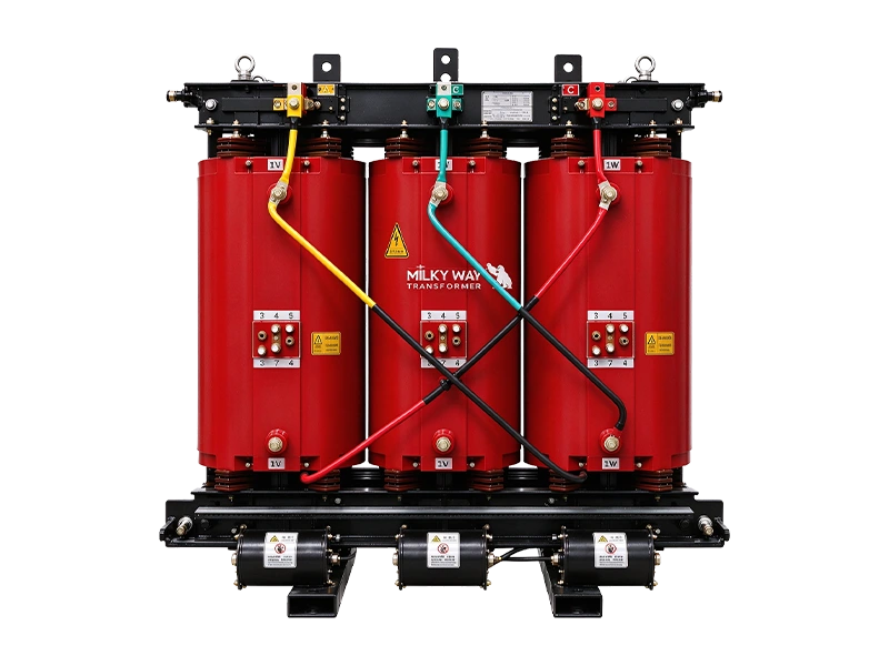
A cast resin dry-type transformer uses resin-encapsulated windings for a dry-type power distribution arrangement. The installation design should coordinate the transformer with its enclosure, ventilation and temperature monitoring requirements. The available dry-type catalogue contains reference tables for several voltage classes and operating configurations. Selection should establish rated capacity, primary and secondary voltage, frequency, vector group and impedance before comparing loss values or dimensions. The required insulation system, temperature rise and cooling duty must be defined for the selected design. Enclosure protection and installation clearance also affect the overall arrangement. For a new project, send the electrical specification and room conditions. For a replacement, include the existing dimensions and cable connection details. Any overload capability, noise value or partial-discharge requirement should be supported by the agreed model specification and test scope. The product should be selected from the approved technical proposal rather than from broad claims that apply to every dry-type transformer.


Features and Benefits
- Dry-type construction provides an alternative to oil-filled equipment.
- Temperature monitoring and enclosure requirements can be coordinated.
Technical Specifications
35kV dry-type off-circuit tap changing power transformer
|
Rated capacity (kVA) |
Rated voltage and tapping range | Vector group |
No load current (%) |
Impedance voltage (%) |
No load losses (kW) |
On load losses (kW) | ||||
|---|---|---|---|---|---|---|---|---|---|---|
|
HV (kV) |
Tapping range (%) |
LV (kV) |
B (100℃) |
F (120℃) |
H (145℃) |
|||||
| 800 |
35 36 37 38.5 |
±2×2.5% ±5 |
3.15 6 6.3 10 10.5 11 |
Dyn11 Yd11 Yyn0 |
0.85 | 6.0 | 2.02 | 8.87 | 9.4 | 10.0 |
| 1000 | 0.85 | 2.40 | 10.3 | 10.9 | 11.6 | |||||
| 1250 | 0.75 | 2.81 | 12.1 | 12.9 | 13.8 | |||||
| 1600 | 0.75 | 3.32 | 14.6 | 15.4 | 16.5 | |||||
| 2000 | 0.65 | 7.0 | 3.80 | 17.2 | 18.2 | 19.5 | ||||
| 2500 | 0.65 | 4.37 | 20.6 | 21.8 | 23.3 | |||||
| 3150 | 0.60 | 8.0 | 5.42 | 23.1 | 24.5 | 26.2 | ||||
| 4000 | 0.60 | 6.31 | 27.7 | 29.4 | 31.5 | |||||
| 5000 | 0.55 | 7.53 | 32.9 | 34.9 | 37.4 | |||||
| 6300 | 0.55 | 8.91 | 38.5 | 40.8 | 43.7 | |||||
| 8000 |
Dyn11 Yd11 YNd11 |
0.45 | 9.0 | 10.1 | 43.4 | 46.0 | 49.3 | |||
| 10000 | 0.45 | 11.6 | 52.4 | 55.5 | 59.4 | |||||
| 12500 |
6 6.3 10 10.5 11 |
0.35 | 14.1 | 60.9 | 64.6 | 69.1 | ||||
| 16000 | 0.35 | 17.3 | 71.7 | 76.0 | 81.3 | |||||
| 20000 | 0.30 | 10.0 | 20.6 | 80.6 | 85.5 | 91.5 | ||||
| 25000 | 0.30 | 24.3 | 95.3 | 101 | 108 | |||||
* Values are reference data; project guarantees are confirmed in the technical agreement.
35kV dry load regulating power transformer
|
Rated capacity (kVA) |
Rated voltage and tapping range | Vector group |
No load current (%) |
Impedance voltage (%) |
No load losses (kW) |
On load losses (kW) |
||||
|---|---|---|---|---|---|---|---|---|---|---|
|
HV (kV) |
Tapping range (%) |
LV (kV) |
B (100℃) |
F (120℃) |
H (145℃) |
|||||
| 2000 |
35 36 37 38.5 |
±4×2.5% |
6 6.3 10 10.5 11 |
Dyn11 Yd11 |
0.65 | 7.0 | 4.05 | 17.9 | 19.0 | 20.3 |
| 2500 | 0.65 | 4.69 | 21.3 | 22.6 | 24.2 | |||||
| 3150 | 0.60 | 8.0 | 5.67 | 24.0 | 25.4 | 27.2 | ||||
| 4000 | 0.60 | 6.64 | 28.7 | 30.4 | 32.6 | |||||
| 5000 | 0.50 | 7.85 | 34.0 | 36.1 | 38.6 | |||||
| 6300 | 0.50 | 9.27 | 39.4 | 41.8 | 44.7 | |||||
| 8000 | 0.45 | 9.0 | 10.6 | 44.8 | 47.5 | 50.8 | ||||
| 10000 | 0.45 | 12.1 | 53.9 | 57.1 | 61.2 | |||||
| 12500 | 0.35 | 14.7 | 62.7 | 66.5 | 71.1 | |||||
| 16000 | 0.35 | 18.1 | 73.8 | 78.2 | 83.7 | |||||
| 20000 | 0.30 | 10.0 | 21.4 | 83.0 | 88.0 | 94.2 | ||||
| 25000 | 0.30 | 25.2 | 98.2 | 104 | 111 | |||||
* Values are reference data; project guarantees are confirmed in the technical agreement.
20kV dry off-circuit tap changing distribution transformer
|
Rated capacity (kVA) |
Rated voltage and tapping range | Vector group |
No load current (%) |
Impedance voltage (%) |
No load losses (kW) |
On load losses (kW) |
||||
|---|---|---|---|---|---|---|---|---|---|---|
|
HV (kV) |
Tapping range (%) |
LV (kV) |
B (100℃) |
F (120℃) |
H (145℃) |
|||||
| 50 |
20 22 24 |
±2.5 ±5 |
0.4 |
Yyn0 Dyn11 |
1.8 | 6.0 | 0.305 | 1.16 | 1.23 | 1.31 |
| 100 | 1.6 | 0.485 | 1.87 | 1.99 | 2.13 | |||||
| 160 | 1.4 | 0.600 | 2.33 | 2.47 | 2.64 | |||||
| 200 |
±2×2.5 ±5 |
1.4 | 0.655 | 2.77 | 2.94 | 3.14 | ||||
| 250 | 1.2 | 0.755 | 3.22 | 3.42 | 3.66 | |||||
| 315 | 1.2 | 0.870 | 3.85 | 4.08 | 4.36 | |||||
| 400 | 1.0 | 1.03 | 4.65 | 4.84 | 5.18 | |||||
| 500 | 1.0 | 1.21 | 5.46 | 5.79 | 6.19 | |||||
| 630 | 0.90 | 1.37 | 6.45 | 6.84 | 7.32 | |||||
| 800 | 0.90 | 1.57 | 7.79 | 8.26 | 8.84 | |||||
| 1000 | 0.80 | 1.86 | 9.22 | 9.78 | 10.4 | |||||
| 1250 | 0.80 | 2.14 | 10.8 | 11.5 | 12.3 | |||||
| 1600 | 0.80 | 2.51 | 13.0 | 13.8 | 14.8 | |||||
| 2000 | 0.60 | 2.91 | 15.4 | 16.3 | 17.5 | |||||
| 2500 | 0.60 | 3.48 | 18.2 | 19.3 | 20.7 | |||||
| 2000 | 0.60 | 8.0 | 2.91 | 16.8 | 17.8 | 19.1 | ||||
| 2500 | 0.60 | 3.48 | 20.0 | 21.2 | 22.7 | |||||
* Values are reference data; project guarantees are confirmed in the technical agreement.
10kV dry three-phase double-winding non-excitation regulating distribution transformer
|
Rated capacity (kVA) |
Rated voltage and tapping range | Vector group |
No load current (%) |
Impedance voltage (%) |
No load losses (kW) |
On load losses (kW) |
||||
|---|---|---|---|---|---|---|---|---|---|---|
|
HV (kV) |
Tapping range (%) |
LV (kV) |
B (100℃) |
F (120℃) |
H (145℃) |
|||||
| 30 |
6 6.3 6.6 10 10.5 11 |
±2.5 ±5 |
0.4 |
Yyn0 Dyn11 |
2.0 | 4.0 | 0.105 | 0.605 | 0.64 | 0.685 |
| 50 | 2.0 | 0.155 | 0.845 | 0.9 | 0.965 | |||||
| 80 | 1.5 | 0.21 | 1.16 | 1.24 | 1.33 | |||||
| 100 | 1.5 | 0.23 | 1.33 | 1.415 | 1.52 | |||||
| 125 | 1.3 | 0.27 | 1.565 | 1.665 | 1.78 | |||||
| 160 | 1.3 | 0.31 | 1.8 | 1.915 | 2.05 | |||||
| 200 |
±2×2.5 ±5 |
1.1 | 0.36 | 2.135 | 2.275 | 2.44 | ||||
| 250 | 0.90 | 0.415 | 2.33 | 2.485 | 2.665 | |||||
| 315 | 0.80 | 0.51 | 2.945 | 3.125 | 3.355 | |||||
| 400 | 0.80 | 0.57 | 3.375 | 3.59 | 3.85 | |||||
| 500 | 0.80 | 0.67 | 4.13 | 4.39 | 4.705 | |||||
| 630 | 0.70 | 0.775 | 4.975 | 5.29 | 5.66 | |||||
| 630 | 0.70 | 6.0~8.0 | 0.75 | 5.05 | 5.365 | 5.76 | ||||
| 800 | 0.70 | 0.875 | 5.895 | 6.265 | 6.715 | |||||
| 1000 | 0.70 | 0.02 | 6.885 | 7.315 | 7.885 | |||||
| 1250 | 0.70 | 1.205 | 8.19 | 8.72 | 9.335 | |||||
| 1600 | 0.70 | 1.415 | 9.945 | 10.555 | 11.32 | |||||
| 2000 | 0.60 | 1.76 | 12.24 | 13.005 | 14.005 | |||||
| 2500 | 0.60 | 2.08 | 14.535 | 15.445 | 16.605 | |||||
* Values are reference data; project guarantees are confirmed in the technical agreement.
35kV dry three-phase double-winding off-circuit tap changing new energy generation side for photovoltaic, wind power, energy storage transformers
|
Rated capacity (kVA) |
Rated voltage and tapping range | Vector group |
No load current (%) |
Impedance voltage (%) |
No load losses (kW) |
On load losses (kW) |
||||
|---|---|---|---|---|---|---|---|---|---|---|
|
HV (kV) |
Tapping range (%) |
LV |
B (100℃) |
F (120℃) |
H (145℃) |
|||||
| 1000 | 35~38.5 |
±2×2.5 ±5 |
0.4~1.14 |
Dyn11 Yd11 Yyn0 |
0.85 | 6.0~14.0 | 1.4 | 8.8 | 9.4 | 10.1 |
| 1250 | 0.75 | 1.6 | 10.7 | 11.4 | 12.2 | |||||
| 1600 | 0.75 | 1.9 | 13.1 | 13.9 | 14.9 | |||||
| 2000 | 0.65 | 2.2 | 15.4 | 16.4 | 17.5 | |||||
| 2500 | 0.65 | 2.6 | 18.5 | 19.6 | 21.0 | |||||
| 3000 | 0.60 | 3.2 | 20.3 | 21.6 | 23.1 | |||||
| 3150 | 0.60 | 3.5 | 20.7 | 22.1 | 23.5 | |||||
| 4000 | 0.60 | 4.1 | 24.9 | 26.5 | 28.2 | |||||
| 4500 | 0.55 | 4.4 | 27.4 | 29.1 | 31.1 | |||||
| 5000 | 0.55 | 4.8 | 29.6 | 31.4 | 33.6 | |||||
| 6300 | 0.55 | 5.7 | 34.6 | 36.7 | 39.2 | |||||
| 8000 |
Dyn11 Yd11 YNd11 |
0.45 | 6.9 | 41.7 | 44.3 | 47.3 | ||||
| 10000 | 0.45 | 8.2 | 49.0 | 52.1 | 55.7 | |||||
* Values are reference data; project guarantees are confirmed in the technical agreement.
10kV dry three-phase double-winding off-circuit tap changing new energy generation side for photovoltaic, wind power, energy storage transformers
|
Rated capacity (kVA) |
Rated voltage and tapping range | Vector group |
No load current (%) |
Impedance voltage (%) |
No load losses (kW) |
On load losses (kW) |
||||
|---|---|---|---|---|---|---|---|---|---|---|
|
HV (kV) |
Tapping range (%) |
LV (kV) |
B (100℃) |
F (120℃) |
H (145℃) |
|||||
| 500 | 10~12 |
±5 ±2×2.5 |
0.4~1.14 |
Dyn11 Yyn0 |
0.80 | 4.0~10.0 | 0.67 | 4.13 | 4.39 | 4.705 |
| 630 | 0.70 | 0.775 | 4.975 | 5.29 | 5.66 | |||||
| 800 | 0.70 | 0.875 | 5.895 | 6.265 | 6.715 | |||||
| 1000 | 0.70 | 1.02 | 6.885 | 7.315 | 7.885 | |||||
| 1250 | 0.70 | 1.205 | 8.19 | 8.72 | 9.335 | |||||
| 1600 | 0.70 | 1.415 | 9.945 | 10.555 | 11.32 | |||||
| 2000 | 0.60 | 1.76 | 12.24 | 13.005 | 14.005 | |||||
| 2500 | 0.60 | 2.08 | 14.535 | 15.445 | 16.605 | |||||
| 3150 | 0.50 | 2.52 | 17.95 | 19.095 | 20.49 | |||||
* Values are reference data; project guarantees are confirmed in the technical agreement.
Packing & Delivering
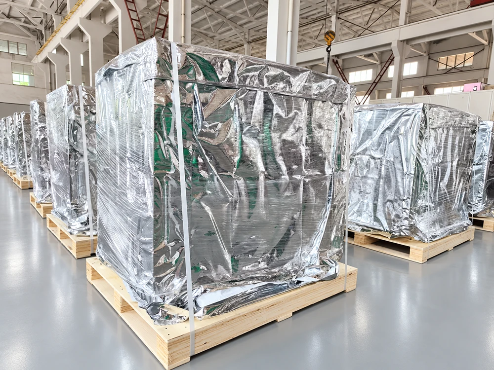
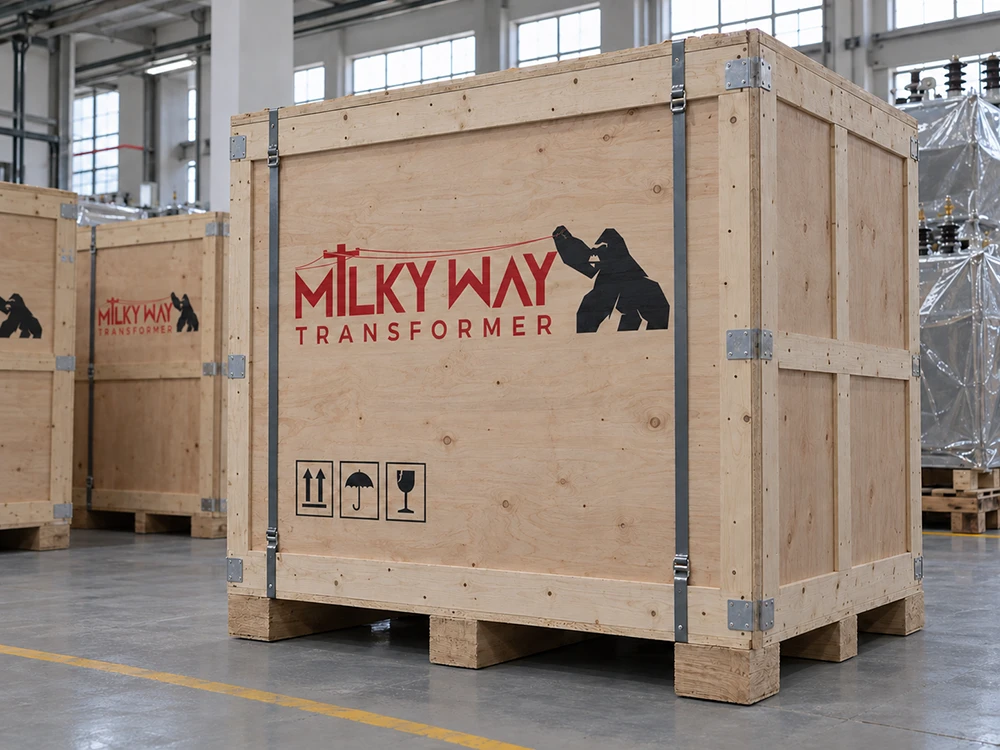
Multi-layer protection and expert logistics for safe global transit.

FAQ's
Q: What Information Is Needed For A Quotation? (Cast Resin Dry-Type Transformer)
A: Capacity; voltages; insulation and temperature rise; enclosure; ventilation; monitoring.
Q: Is Forced-air Overload Capacity Universal?
A: No. Confirm the cooling rating and permitted duty for the selected model.